
This manual explains how to set up, configure IP, wire relays, adjust input/output modes, and troubleshoot the Jinruida J1610MR network switch controller.
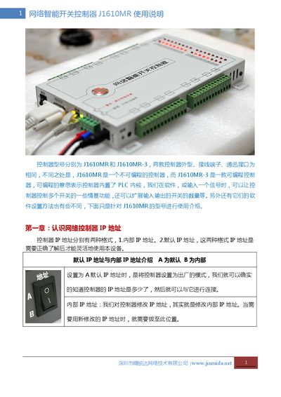
The Jinruida J1610MR is a network‑enabled intelligent switch controller with 16 relay outputs and 16 independent input channels. It supports Modbus TCP/IP, RS485, Ethernet (10 Mbps) and offers remote restart, web‑based control, and active status reporting.
The guide covers IP address configuration (default 192.168.1.250), wiring diagrams for relay and signal inputs, various control modes (trigger, edge, level, etc.), firmware reset procedures, and detailed troubleshooting steps for network and power issues. This manual is written in Chinese.
| Model | J1610MR |
|---|---|
| Working Voltage | 12 V DC |
| Operating Temperature | -20 °C to 70 °C |
| Maximum Humidity | < 90 % RH |
| Power Consumption | 2 A |
| Relay Outputs | 16 independent channels (common, normally‑open, normally‑closed) |
| Input Channels | 16 independent digital inputs |
| Dimensions | 225 mm × 150 mm × 30 mm |
| Weight | 1.2 kg per unit |
| Network Interface | RJ45 Ethernet 10 Mbps |
| Modbus Support | Modbus TCP/IP and Modbus RTU over RS485 |
| RS485 Interface | 600 V per line protection |
| Surge Protection | Up to 1 kV on network port |
| Ground Terminal | Provided for safety grounding |
You can restart by pressing the reset button in the PC software, power‑cycling the 12 V supply, or pressing the indicator button on the controller.
Connect the live line (L) to the common terminal (e.g., 1C). When the relay K is closed, L passes through to the normally‑open contact to power the load; the neutral (N) connects directly to the load.