
Technical datasheet for the IIIC FZ 800 R 17 KF4 IGBT module, detailing electrical, thermal, and mechanical specifications.
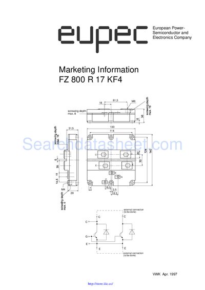
The document provides the full set of technical specifications for the IIIC FZ 800 R 17 KF4 IGBT module. It lists maximum rated values, electrical characteristics such as collector‑emitter voltage and continuous current, as well as gate‑emitter limits.
Additional sections cover thermal resistance, mechanical mounting data, and characteristic curves for turn‑on/turn‑off behavior. The data is presented in both German and English, with graphs illustrating voltage‑current relationships and thermal performance. This manual is written in German.
| Collector‑Emitter Voltage (VCES) | 1700 V |
|---|---|
| Continuous Collector Current (IC) | 800 A |
| Gate‑Emitter Peak Voltage (VGE) | ±20 V |
| Total Power Dissipation (Ptot) | 6250 W |
| Junction‑to‑Case Thermal Resistance (RthJC) | 0.02 °C/W |
| Weight | ≈1500 g |
The maximum collector‑emitter voltage is 1700 V.
The module can carry a continuous collector current of 800 A.
The gate‑emitter peak voltage rating is ±20 V.
The junction‑to‑case thermal resistance is 0.02 °C/W.