
Instruction manual for the Hitachi EH-150 PLC EH-AXH8M analog input module, covering safety precautions, wiring, specifications and switch settings.
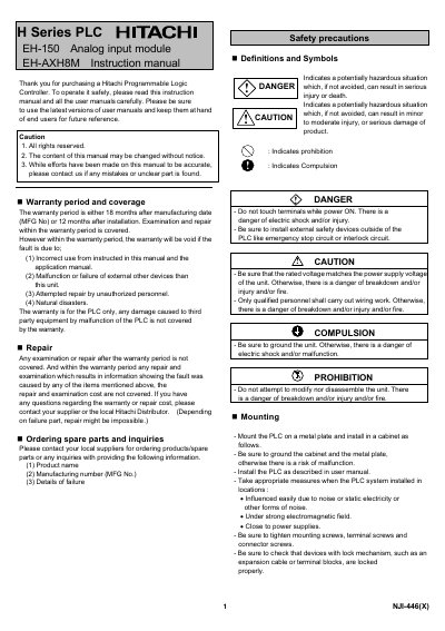
This instruction manual covers the Hitachi EH-AXH8M analog input module used with the NJI-446(X)H series EH-150 programmable logic controller. It explains the module's names and functions, specifications, terminal layout and internal circuit, and the function and voltage/current switch settings.
The manual also provides safety precautions with DANGER/CAUTION definitions, mounting and installation environment guidance, power and I/O wiring instructions, and information on the warranty period and coverage, repair, and ordering spare parts. It references the EH-150 APPLICATION MANUAL (NJI-281*(X)) for further application details.
| Input range (voltage) | 0 to 10 V DC / -10 to 10 V DC (selected by switch) |
|---|---|
| Input range (current) | 0 to 22 mA / 4 to 22 mA |
| Resolution | 1 mV or 1/16384 (14 bits); 0.002 mA or 1/16384 (14 bits) |
| Conversion time | 8.9 ms / 8 channels |
| Overall accuracy | Voltage input ±0.5% or less, current input ±0.8% or less (full scale) |
| Linearity | ±0.1% or less (full scale) |
| Input filter | Enable: approx. 90 ms; Disable: 18 ms or less (to reach 90% after step input) |
| Input impedance | Voltage input differential 200 kΩ; current input 249 Ω |
| Isolation | Between channel and internal bus: photo coupler; between channels: not isolated |
| Number of input channels | 8 ch. differential voltage input or 8 ch. current input (selected per 4 ch.) |
| Weight | Approx. 0.15 kg |
| Internal current consumption (5VDC) | Max. 70 mA |
| External power supply | 24 V DC (+20%, -15%), approx. 0.04 A (approx. 0.3 A at power on) |
| Cable | Shielded pair cable (max. 20 m) |
| I/O assignment | X8W |
| Operational temperature / humidity | 0 - 55 °C / 20 - 90%RH (no condensation) |
| Storage temperature / humidity | -10 - 75 °C / 10 - 90%RH (no condensation) |
The warranty period is either 18 months after the manufacturing date (MFG No) or 12 months after installation.
Use the function switches 1-4 to select the input range for channels 0-3 and 4-7, and set the current/voltage switch accordingly. Switch setting is not effective while power is on, so configure the module before operation without power supplied.
Press the lock button and lift up the module.
Use shielded pair cable with a maximum length of 20 m, connected to the removable M3 terminal block.