
Termination instructions for GORE Aerospace Ethernet Cables using the Harting RJ45 Connector System, covering preparation, assembly, and testing.
This document provides best practice procedures for terminating GORE Aerospace Ethernet Cables with the Harting RJ45 Connector System, specifically optimized for Cat6a protocol performance. It details the necessary tools and materials required for the assembly process.
| Recommended Protocol | Cat6a protocol |
|---|---|
| Heat-shrink sleeving length | 1.5-inch pieces |
| Cable cut length adjustment | minus 1.4 inches |
| Jacket removal mark | 1.1 inches from working end |
| Braid showing after wrapping | 0.70 inches |
| Recommended Tester | Fluke Networks DSX-5000 |
There should be 0.70 inches of braid showing after wrapping the tape around the cable.
The cable must be cut to a length that is at least 1.4 inches shorter than the desired assembly length.
The tape must be wrapped so that exactly 0.70 inches of braid is showing.
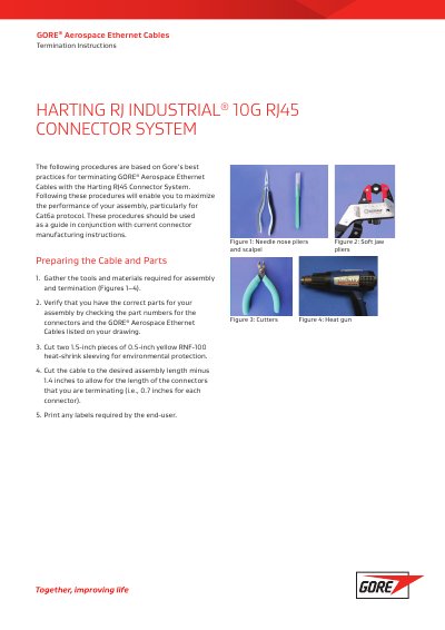
The required tools include needle nose pliers, scalpel, cutters, and a heat gun.