
The FLS F.IMSP1 Interface Module Flow Sensor PLC Instruction Manual explains safe connection, wiring, and specifications for linking FLS Hall‑effect flow…
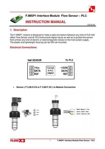
The F.IMSP1 module provides a safe connection between any FLS Hall‑effect flow sensor and PLC or instrument digital inputs, protecting the sensor from electric and electromagnetic noise. Its plastic, lightweight housing is designed for DIN‑rail mounting.
The manual details the electrical connections, including sensor to module and module to PLC wiring, and lists technical data such as a regulated 12‑24 Vdc supply, 11 mA supply current, square‑wave push‑pull output with a maximum of 20 mA, and compliance with ISO 9001 and CE standards.
| Supply voltage | 12 to 24 Vdc regulated |
|---|---|
| Supply current | I Alim= 11 mA @ I Out= 0 |
| Output signal | square wave |
| Output type | Push – Pull |
| Output current | I OutMax < 20 mA |
| Mounting | on DIN rail |
Any kind of FLS Hall‑effect Flow Sensor, such as models F 3.00.H.XX or F 3.00.F.XX, can be safely connected.
The module operates from a regulated 12 to 24 Vdc supply.
It is designed for DIN‑rail mounting.