
Key facts
- Manuals
- 3
- Models
- 1
- Languages
- ZH · EN
- Last added
- 2026-09-29
FLS models by category
Featured FLS manuals
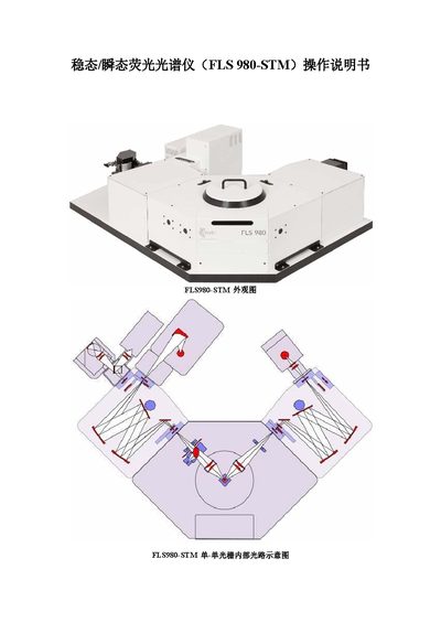
FLS FLS980-STM Fluorescence Spectrometer User Manual
The FLS980-STM is a steady‑state and time‑resolved fluorescence spectrometer capable of measuring liquid and solid samples. It offers steady‑state excitation/emission spectra, fluorescence lifetime from picosecond to millisecond scales, quantum yield using an integrating sphere, and anisotropy measurements with polarizers.
The manual provides detailed instructions for instrument setup, safety precautions, and measurement workflows for both steady‑state and transient fluorescence, including software operation, light‑source selection, slit adjustment, detector cooling, and data acquisition. This manual is written in Chinese.
Covers: Instrument Introduction · Measurement Principles · Precautions Before Measurement · Steady‑State Fluorescence Measurement · Fluorescence Lifetime (Transient) Measurement · Safety and Maintenance Notes
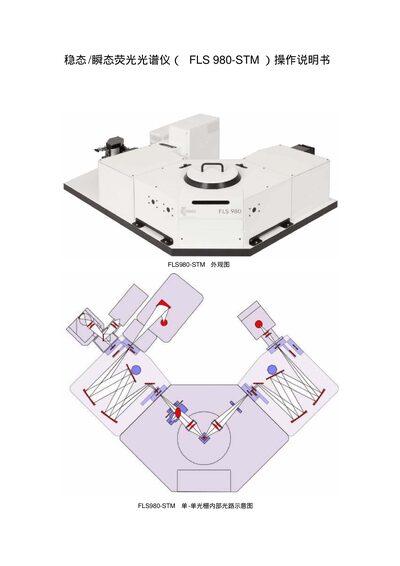
FLS 980-STM User Manual
The FLS980-STM is a fluorescence and phosphorescence measurement system that supports both steady‑state and time‑resolved measurements. It is used for research on polymers, liquids, solids, and photodegradation, providing excitation wavelengths from 200 nm to 400 nm and detection from 200 nm to 870 nm.
The manual details the measurement principles (time‑correlated single photon counting), safety and preparation steps, configuration of light sources and detectors, and the software workflow for data acquisition, processing (normalisation, baseline subtraction, integration, etc.) and export of results, including quantum yield calculations. This manual is written in Chinese.
Covers: 主要功能 · 主要应用 · 主要性能指标 · 仪器测量原理 (SPC) · 测量之前需要特别注意的事项 · 稳态荧光测定
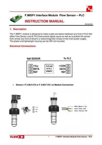
FLS F.IMSP1 Interface Module Flow Sensor PLC Instruction Manual
The F.IMSP1 module provides a safe connection between any FLS Hall‑effect flow sensor and PLC or instrument digital inputs, protecting the sensor from electric and electromagnetic noise. Its plastic, lightweight housing is designed for DIN‑rail mounting.
The manual details the electrical connections, including sensor to module and module to PLC wiring, and lists technical data such as a regulated 12‑24 Vdc supply, 11 mA supply current, square‑wave push‑pull output with a maximum of 20 mA, and compliance with ISO 9001 and CE standards.
Covers: Description · Electrical Connections · Technical Data · Mounting Information · Standard & Approvals
Latest FLS manuals
FLS FLS980-STM Fluorescence Spectrometer User Manual
User Manual 9 pages · 1.7 MB · ZHThe FLS FLS980-STM Fluorescence Spectrometer User Manual describes functions, performance specs, measurement principles, and step‑by‑step operating procedures.
FLS 980-STM User Manual
User Manual 13 pages · 1.5 MB · ZHThis manual explains how to operate the FLS980-STM instrument, covering its functions, measurement principles, setup steps, and data processing for…
FLS F.IMSP1 Interface Module Flow Sensor PLC Instruction Manual
User Manual 2 pages · 340 KB · ENThe FLS F.IMSP1 Interface Module Flow Sensor PLC Instruction Manual explains safe connection, wiring, and specifications for linking FLS Hall‑effect flow…
Which document do I need?
User Manual
Day-to-day operation, settings and troubleshooting. Start here if the product is already set up.
Questions answered in FLS manuals
What must be done with the sample chamber door before opening the F980 software?
The sample chamber door must be open before the software is started.
What slit setting is required before changing light sources or adjusting the sample?
Set the slit (Δλ) to its minimum of 0.02 nm before any light‑source change or sample adjustment.
What is the lifetime measurement range of the FLS980-STM?
The instrument can measure lifetimes from 100 ps up to 10 s.
From: FLS 980-STM User Manual
Which wavelength range can the detector cover?
The detector operates over a wavelength range of 200 nm to 870 nm.
From: FLS 980-STM User Manual
What type of sensors can be connected to the F.IMSP1 module?
Any kind of FLS Hall‑effect Flow Sensor, such as models F 3.00.H.XX or F 3.00.F.XX, can be safely connected.
From: FLS F.IMSP1 Interface Module Flow Sensor PLC Instruction Manual
What supply voltage does the module require?
The module operates from a regulated 12 to 24 Vdc supply.
From: FLS F.IMSP1 Interface Module Flow Sensor PLC Instruction Manual