
Installation and initial setup instructions for Fisher DVC6200 Series digital valve controllers.
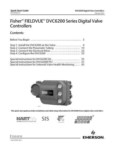
This Quick Start Guide walks users through installing the DVC6200 digital valve controller on a valve, connecting pneumatic tubing and electrical wiring, and configuring the controller for operation. It also includes special instructions for SIS, PST, and solenoid‑valve health monitoring variants.
Safety cautions, mounting guidelines, and wiring diagrams are provided to ensure proper and safe integration of the controller into process control systems.
| Fastener torque (4 mm screws) | 2.37 N·m (21 lbf·in) |
|---|---|
| Minimum tubing ID for DVC6200 SIS High Cv (HCv2) | 11.7 mm (0.46 in) |
| Minimum tubing ID for DVC6200 SIS High Cv (HCv3) | 16.5 mm (0.65 in) |
| Digital valve controller current draw | ≈ 8 mA |
| Maximum solenoid valve circuit voltage | 30 VDC |
| Maximum solenoid valve circuit current | 1 A |
| Line conditioner voltage drop | ≈ 2.0 V |
Use 2.37 N·m (21 lbf·in) for 4 mm screws and 5.08 N·m (45 lbf·in) for 5 mm screws.
It draws approximately 8 mA during operation.
The solenoid valve circuit must be 30 VDC or less with a maximum current of 1 A.