
Installation and operating instructions for the Equilibar EPC closed-loop electronic pressure controller, with specifications, plumbing, wiring and calibration.
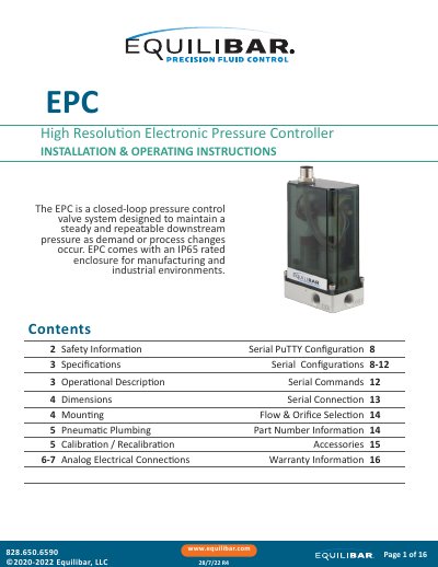
The Equilibar EPC is a closed-loop pressure control valve system that maintains a steady and repeatable downstream pressure as demand or process changes occur. It is supplied in an IP65 rated enclosure for manufacturing and industrial environments, and each unit contains two internal solenoid valves, a manifold, an electronic control circuit board and a pressure transducer. This 16-page document gives the installation and operating instructions, including safety precautions, specifications, dimensions, mounting, pneumatic plumbing and calibration.
The text explains how the EPC works: the inlet solenoid valve opens proportionally to the control circuit current to raise pressure, while the exhaust valve vents to atmosphere to lower it, and the internal transducer feeds a pressure signal back to the control circuit. It also covers analog electrical connections and pin-out for the 0-10 VDC command signal, serial PuTTY configuration and serial commands, flow and orifice selection, part number information, accessories and warranty information. EPC units are calibrated at the factory to NIST standards, and any change of calibration must be done by returning the unit to Equilibar.
| Electrical supply voltage | 15-24 VDC |
|---|---|
| Supply current | <250 mA max. |
| Command signal options | 0-10 VDC, 4-20 mA (differential), 3.3 V Serial Digital |
| Accuracy | <±0.25% of Full Scale |
| Resolution | < 5 mV |
| Linearity | ±0.05% BFSL |
| Max hysteresis | ±0.05% of Full Scale |
| Response time | < 20 ms typical (application dependent) |
| Pressure range | full vac - 150 psig (10.3 barg) |
| Medium | Clean, dry, non-corrosive gases |
| Operating temperature | 32 to 120 °F (0 to 49°C) |
| Recommended filtration | 40 micron nominal |
| Port size | 1/8” NPT |
| Housing | Polycarbonate/ABS blend |
| Protection rating | IP65 |
The EPC requires 15 to 24 VDC on Pin 8 of the electrical connector and uses a 0 to 10 VDC command signal on Pin 1. The power supply ground, command source ground and Pin 3 must be tied together.
Yes. The EPC is not sensitive to position and may be mounted in any orientation, and it comes standard with top-down mounting holes for flat surfaces.
If the calibration needs to be changed or modified, the unit must be returned to Equilibar; any attempt to recalibrate in the field without prior authorization will void the warranty.
A filter with at least 40-micron filtration is recommended before the inlet, because the EPC is extremely sensitive to dirt and debris.