
Installation guide for the Elecraft HG 144‑K internal transverter, covering specs, wiring and setup for the K3 transceiver.
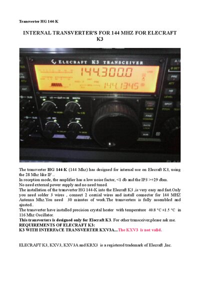
The HG 144‑K is an internal transverter designed for the Elecraft K3, converting a 28 MHz IF to a 144 MHz output. It features a low‑noise amplifier (<1 dB NF) and high third‑order intercept (>+29 dBm) without needing an external power supply.
The manual provides step‑by‑step installation instructions, including soldering three wires, connecting two coaxial cables, and mounting the antenna connector. After assembly, the transverter is enabled via the K3 menu (XV1 settings) and ready for operation on the 144 MHz band.
| Installation | Internal (Inside ELECRAFT K3) |
|---|---|
| Dimensions | 73 mm × 73 mm × 30 mm |
| Supply Voltage | 12 VDC (internal) |
| Current Drain (receive) | 130 mA |
| Frequency Range | 144 000‑146 000 MHz |
| Transmitter Power Output | 8 W at 1.1:1 SWR (50 Ω load) |
| Operating Modes | SSB, FM, CW, Digital, etc. |
| IF Range | 28 000‑30 000 MHz |
| TX RF Mixer | Mini Circuits ADEX-10H (+17 dBm) |
| Receiver Noise Figure | <1 dB |
| 3rd‑Order Intercept | >+29 dBm |
The installation requires about 30 minutes of work.
It uses the internal 12 VDC supply from the Elecraft K3.
Set XV1 ON to YES, XV1 RF to 144, XV1 IF to 28, and XV1 PWR to L 1.00 in the K3 menu.