
Instruction manual for the EP-500 electronic regulator and EPA-300 booster amp, covering composition, specs, installation, wiring, adjustment, and maintenance.
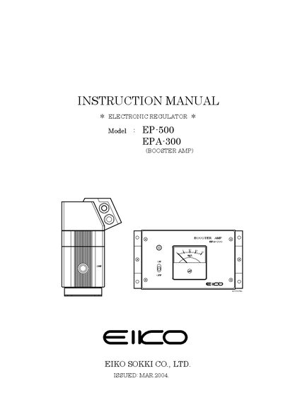
The manual describes the EP-500 electronic regulator paired with the EPA-300 booster amp. It details the unit composition, technical specifications, and required clean air supply for reliable operation.
Installation procedures, pneumatic circuit diagrams, wiring guidelines, adjustment steps, and routine maintenance are provided to ensure proper setup and long‑term performance.
| Power source | AC 100V or AC 200V (50/60 Hz) |
|---|---|
| Input voltage | DC 0–5 V |
| Output current | DC 4–20 mA |
| Linearity | ±1.0 %FS (±0.85 %FS for other models) |
| Hysteresis | 2.0 %FS (1.7 %FS for other models) |
| Input impedance | 500 Ω or less |
| Maximum flow rate | 2000 L/min (ANR) |
| Air consumption | 3 L/min (ANR) |
| Step response time | Less than 2 sec (no‑load) |
| Connection pipe size | Rc 1/4" |
The output current is set by factory‑adjusted VRs; reference values are 4 mA at 0 V and 20 mA at 5 V, with a tolerance of ±0.1 mA.
Clean, dry air filtered and free of oil mist is required; supply pressure should be adjusted with a manual regulator.
The orifice should be inspected and cleaned at least once a year to prevent clogging.
Use a 2‑wire shielded cable with a cross‑section of 0.5–1.5 mm², not exceeding 30 m in length.