
The TX-DA102D IGBT driver manual from Beijing Luomu Yuan details specifications, protection features, wiring and setup for high‑power IGBT modules up to 1700 V.
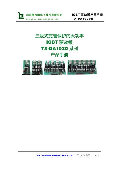
The TX-DA102D series is a high‑power IGBT driver board that can drive any IGBT below 1700 V. It offers up to 4.5 W per channel, 30 A output current, three‑stage over‑current protection, and configurable gate‑charge settings. The board works with a single 12‑30 V DC supply and supports various unit configurations (1, 2, 4, 6, 7 units).
The manual provides a block diagram, electrical parameters, waveform illustrations, mechanical dimensions, connector pin assignments, application circuit examples, and detailed instructions for setting protection thresholds, dead‑time, delay, soft‑shutdown and restart times. It also includes a FAQ section and references to related products. This manual is written in Chinese.
| Maximum output power per channel | 4.5 W |
|---|---|
| Output current | ±30 A |
| Output charge | 40 µC |
| Input voltage range | 12‑30 V DC |
| Minimum gate resistance | 0.5 Ω |
| Operating temperature range | -40 °C to 85 °C |
| Storage temperature range | -40 °C to 120 °C |
The series offers 1‑unit, 2‑unit, 4‑unit, 6‑unit and 7‑unit board options.
The driver operates from a single 12‑30 V DC supply, with a typical value of 15 V.