
This document provides instructions for using MPLAB ICD2, including its working principle, installation and configuration, debugging mode, and troubleshooting.
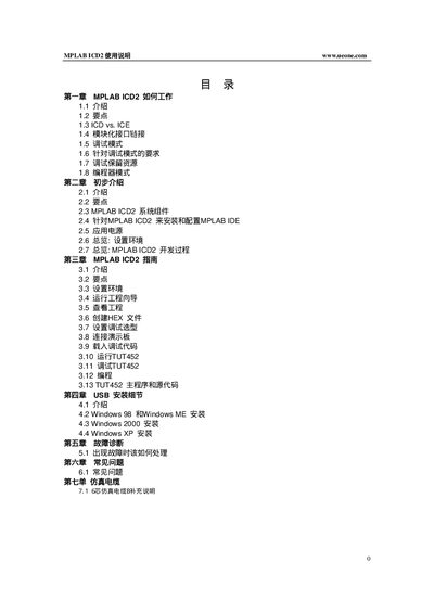
This manual explains how the MPLAB ICD2 works, its hardware interfaces, and the steps required to install and configure the MPLAB IDE for programming and debugging PIC microcontrollers. It covers power options, USB and RS‑232 connections, and the modular six‑pin interface cable.
The guide also provides troubleshooting tips, FAQs, and detailed wiring diagrams for proper connection of VPP, PGC, PGD, VDD, and VSS pins, as well as information on reserved resources used during debugging. This manual is written in Chinese.
| Interface cable | Six‑pin modular cable |
|---|---|
| Programming voltage | Applied to VPP pin |
| Power source (USB) | Can be powered from PC USB port |
| Power source (RS‑232) | Requires external power adapter |
Use the six‑pin modular interface cable and connect the VPP/MCLR, PGC, PGD, VDD, and VSS pins as shown in the wiring diagrams.
First install the MPLAB IDE, then install the USB drivers from the DriversXX folder before connecting the ICD2 via USB.
Yes, by selecting the Programmer > Program option, the ICD2 will only program the target device and will not enable debugging features.