
MAST5-6A IGBT driver board is a board product with 6 IGBT drivers, 6 isolated DC-DCs, current source drive mode, VCE detection mode short circuit protection, undervoltage protection, IGBT gate TVS protection elements, power indicator, pulse indicator and other functions.
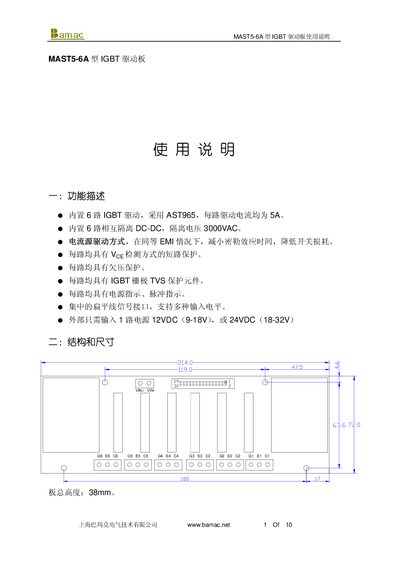
This manual provides a complete overview of the MAST5-6A IGBT driver board, including its six isolated driver channels, built‑in DC‑DC converters, and protection features such as short‑circuit, undervoltage and TVS protection. Detailed pin definitions, signal input requirements, and power supply connections are listed with wiring diagrams.
Technical parameters such as supply voltage ranges, current limits, power consumption, operating temperature limits and electrical ratings are presented, along with guidance on layout, magnetic interference mitigation, and short‑circuit protection timing adjustments. This manual is written in Chinese.
| Number of driver channels | 6 |
|---|---|
| Per‑channel driver current | 5 A |
| Isolation voltage | 3000 V AC |
| Supply voltage (24 V version) range | 18‑32 V |
| Supply voltage (12 V version) range | 9‑18 V |
| Maximum power consumption | 20 W |
| Operating temperature range | -25 °C to 70 °C |
| Input voltage range (VI) | -7 V to +7 V |
| Typical rise time (no load) | 0.1 µs |
The board accepts either 12 V or 24 V DC applied to the VIN+ and VIN‑ terminals, observing correct polarity.
Each channel includes short‑circuit protection, undervoltage protection, TVS gate protection, and power/pulse indicator LEDs.
By adding a capacitor (e.g., 1000 pF adds about 1 µs) to the Cx pins (x = 1‑6), the protection delay can be increased.