
Circuit description of the TCT40-16T33/16R33 ultrasonic sensor: 40 kHz transmit and receive circuits, amplifiers, LM311 shaping and distance measurement.
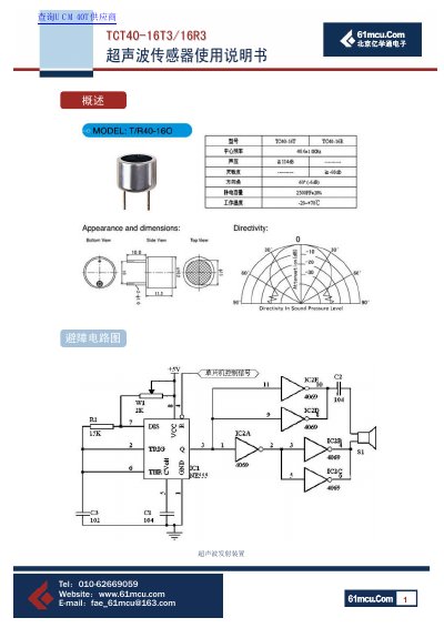
This short Chinese-language document describes the circuits used with the TCT40-16T33/16R33 ultrasonic sensor pair. It covers a transmit stage built around an NE555 astable multivibrator whose frequency is set by W1, R1 and C3 and whose output is amplified by a CD4049 to drive the transducer, plus an obstacle-avoidance circuit diagram.
The receive side couples the weak transducer signal through two operational amplifier stages (gains of -50 and -20, total gain 1000) and shapes it with an LM311 comparator to give a TTL-level signal for a microcontroller. A second ranging circuit uses an audio decoder LM567 and an NE5532 preamplifier, and the text explains the 40 kHz pulse program, the s=340t/2 ranging principle, and how a roughly 1 ms detection delay avoids residual-wave interference. This manual is written in Chinese.
| Sensor drive signal | 40 kHz pulse |
|---|---|
| Speed of sound used in calculation | 340 m/s |
| Receiver total gain (circuit I) | 1000 |
| First amplifier stage gain | -50 |
| Second amplifier stage gain | -20 |
| LM567 input threshold | greater than 25 mV |
| Preamplifier gain (circuit II) | 10000 |
| Ultrasonic burst duration | 200 ms |
| Detection delay to skip residual wave | about 1 ms |
It times the interval until the reflected wave returns and computes s=340t/2, using 340 m/s as the speed of sound in air.
An NE555 astable multivibrator sets the frequency through W1, R1 and C3, and a CD4049 amplifies the signal to drive the transducer.
The two stages give -50 and -20, for a total gain of A=A1*A2=1000.
The timer starts at transmission but echo detection is enabled only after a wait of about 1 ms, so the residual wave is not detected.