
The MCP2502X/5X is an I/O extender for Controller Area Network (CAN) systems, supporting a maximum bus rate of 1 Mb/s for CAN V2.0B active. It features a programmable mask register, programmable filters, three automatic transmit buffers, two message receive buffers, and does not require synchronization or configuration of messages. The device also has non-volatile memory for user configuration, allowing automatic loading of configurations on power-up. It supports eight general-purpose IO lines that can be individually selected as inputs or outputs, with the ability to send messages when the pin state changes. The MCP2505X device additionally includes four 10-bit analog input channels with programmable conversion clock and VREF source. The device can be modified through CAN bus messages and has default configuration memory that can be programmed online. It also supports optional 1-wire CAN bus operation. The MCP2502X/5X devices operate on low power CMOS technology, with a working voltage range of 2.7V to 5.5V and low standby current. The devices are available in 14-pin PDIP and SOIC packages, and operate in industrial and extended temperature ranges.
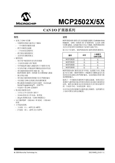
The MCP2502X/5X series is a CAN I/O extender that implements the CAN V2.0B protocol with up to 1 Mbit/s bus speed. It offers programmable mask registers, filters, three transmit buffers, two receive buffers, and optional 1‑wire CAN operation, making it suitable for industrial control and automotive applications.
The document details the device architecture, including the CAN module, finite‑state machine, CRC, error management logic, and bit‑timing logic. It lists the pin assignments for PDIP and SOIC packages, describes the configuration registers (CNF1‑CNF3), and provides timing parameters such as propagation, phase‑segment, and synchronization jump width settings. This manual is written in Chinese.
| Maximum CAN bus speed | 1 Mbit/s |
|---|---|
| Supply voltage range | 2.7 V to 5.5 V |
| Active current (typical) | 10 mA |
| Standby current (CAN sleep mode) | 30 µA |
| Package options | 14‑pin PDIP (300 mil) and SOIC (150 mil) |
The device supports a maximum CAN bus speed of 1 Mbit/s.
It provides three automatic transmit buffers and two receive buffers.
Yes, the device includes an optional 1‑wire CAN bus operation mode.