
This document describes the application considerations and working modes of the SH69P43/P42 simulator, as well as the simulation process of user programs. The simulator can simulate all the functions of the SH69P43 (or SH69P42) chip, helping users develop their user programs.
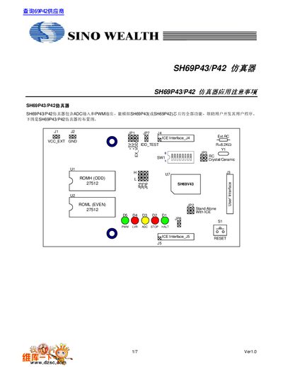
The SH69P43/P42 emulator provides ADC input and PWM output to simulate the full functionality of the SH69P43 or SH69P42 chip. It can operate in ICE (connected to a mother‑board) or Stand‑alone mode using an EPROM socket.
The manual details programming precautions, interface pin assignments, jumper configurations for voltage and clock source selection, and LED status indicators, along with power specifications and reset procedures. This manual is written in Chinese.
| Power supply voltage (VCC_EXT) | +5 V ±5 % |
|---|---|
| Maximum output current (3 V supply) | 100 mA |
| Oscillator frequency range (default) | 2 MHz – 8 MHz |
The emulator can run in ICE (connected to a mother‑board) mode or Stand‑alone mode using an EPROM socket.
When using the 3 V supply, the emulator can provide up to 100 mA of current.