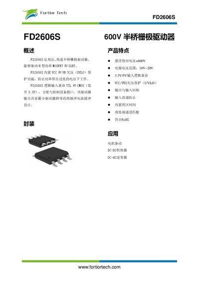
Technical datasheet for the Fortior FD2606S 600 V half‑bridge gate driver with specifications, pinout and typical application circuits.
About this manual
The FD2606S is a high‑voltage, high‑speed half‑bridge gate driver capable of driving N‑type power MOSFETs and IGBTs. It includes built‑in VCC and VB undervoltage (UVLO) protection, TTL/CMOS compatible logic inputs, and a high‑pulse‑current buffer design.
The document provides absolute maximum ratings, recommended operating conditions, electrical parameters, pin configuration, typical application schematics, and package dimensions for designers integrating the driver into motor drives, DC‑DC converters, or DC‑AC inverters. This manual is written in Chinese.
What's inside
- Overview
- Features
- Absolute Maximum Ratings
- Recommended Operating Conditions
- Electrical Parameters
- Pin Configuration
- Typical Application Circuit
- Package Dimensions
- Mechanical Drawing
Specifications
| High‑side floating absolute voltage (VB) | -0.3 ~ 625 V |
|---|
| Supply voltage range (VCC) | 10 V ~ 20 V |
|---|
| Logic input voltage compatibility | 3.3 V/5 V TTL and CMOS |
|---|
| High‑side output voltage (VHO) | VS‑0.3 ~ VB+0.3 V |
|---|
| Dead‑time range | 470 ns ~ 650 ns |
|---|
Frequently asked questions
What is the maximum high‑side voltage the driver can handle?
The absolute maximum high‑side floating voltage is up to 625 V.
Which logic levels are supported for the inputs?
Inputs are compatible with TTL and CMOS logic, supporting 3.3 V and 5 V levels.
What is the recommended supply voltage range for VCC?
The recommended VCC supply voltage is between 10 V and 20 V.
Does the device include undervoltage protection?
Yes, it has built‑in VCC and VB undervoltage (UVLO) protection functions.