
The Dell™ Latitude™ E5400 and E5500 Service Manual provides information on how to troubleshoot the Dell™ Latitude™ E5400 and E5500 notebook computers.
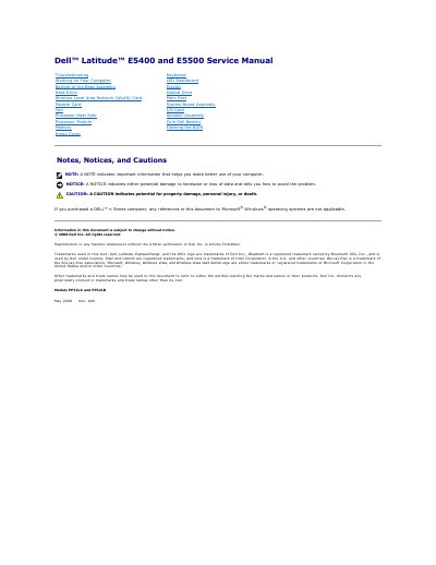
This service manual provides removal and installation procedures for components in Dell Latitude E5400 and E5500 computers, including the bottom of the base assembly, display, hard drive, optical drive, WLAN card, palm rest, modem card, system board, fan, I/O card, processor heat sink, speaker assembly, processor module, coin-cell battery, memory, and hinge cover.
It also covers recommended tools, safety steps before and after working on the computer, flashing the BIOS from a CD or the hard drive, and troubleshooting.
| Models | PP32LA and PP32LB |
|---|---|
| E5400 bottom base assembly fasteners | Five captive screws |
| E5500 bottom base assembly fastener | M2.5 x 8-mm screw |
Loosen the five captive screws, pry up on the recess near the slender edge, slide the assembly toward the left side of the computer, and lift it up.
Insert the BIOS-update CD, restart the computer, press F12 at the Dell logo, select CD-ROM at the Boot Device Menu, and follow the on-screen instructions.
A small flat-blade screwdriver, Phillips screwdriver, small plastic scribe, and a flash BIOS update.
Use a flat, clean work surface, shut down the computer, disconnect power and cables, remove installed cards and the battery, and ground yourself.