
The ViewFlex Camera is a versatile camera that can take both photos and videos. It features a 12-megapixel camera, 1080p HD video recording, 3x optical zoom, a 2.7-inch LCD screen, a built-in flash, and support for SD card expansion.
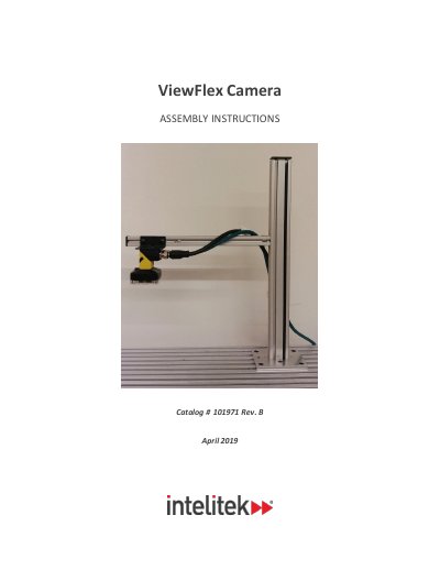
This document from Intelitek gives the assembly and wiring instructions for the ViewFlex camera setup, Catalog # 1019 71 Rev. B, dated April 2019. It covers assembling the camera stand that holds the Cognex Vision Sensor (QC camera, Cognex #00-1430-0000) in position for ViewFlex operations, then wiring the power through the camera's breakout cable. The manual states that it only details assembly and wiring, and that use of the Cognex 2000 itself is covered in the Cognex 2000 user manual.
The assembly section explains mounting the stand base to a slotted table with four M5 Allen screws and M5 slot nuts, to a Formica table with four pan head Phillips screws, or to a CIM track with an angular connector (catalog number 110633). It then covers attaching the camera to the bracket with two M3 Phillips screws, connecting the green Ethernet cable and black breakout cable, and securing the cables with clamps and ties. The wiring section connects the black ground and red +24V DC wires of the breakout cable to a 24V DC adapter and confirms power at the vision sensor. An appendix lists the breakout cable wire colors and signal names.
| Breakout cable power supply requirement | 24V DC adapter |
|---|---|
| Camera to bracket screws | Two M3 Phillips screws |
| Base mounting on a slotted table | Four M5 Allen screws and four M5 slot nuts |
| Base mounting on a Formica table | Four pan head Phillips screws |
| CIM track connector catalog number | 110633 |
| Red wire signal | +24VDC |
| Black wire signal | GND (ground connection) |
The camera is attached to the bracket with two M3 Phillips screws, which must be fastened so the camera is secure.
It requires connection to a 24V DC adapter first.
The black wire is the ground connection, while the red wire is the +24V DC connection.
Make sure the vision sensor's green power LED is lit.