
Grounding and short-circuit fault indicator is mainly used to detect, indicate, transmit fault signals and send remote indication alarm, and also has memory and recovery function. It can make maintenance personnel accurately judge the fault occurrence interval, improve the fault analysis ability, so as to quickly eliminate the fault, reduce the outage area, and shorten the outage time. It plays an important role in ensuring the safe operation of the power grid and improving the power supply quality of the power grid.
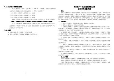
This manual details the installation, wiring, and operation of a panel-mounted 485 communication fault indicator designed for grid monitoring. It includes instructions for connecting current sensors, resetting alarms, and technical specifications such as fault thresholds and power requirements. The device detects and indicates short-circuit and grounding faults, with remote alarm transmission and automatic/manual reset features.
The unit is intended for use in high-voltage switchgear and distribution systems up to 35kV, with a compact form factor (97x50x64mm) and modular components including three short-circuit sensors, one grounding sensor, and four optical fibers. This manual is written in Chinese.
| Short Circuit Fault Threshold | ≥150A (factory set to 800A, customizable) |
|---|---|
| Ground Fault Threshold | 20A–50A (factory set to 20A, customizable) |
| Conductor Wire Diameter | 25mm² ≤ d ≤ 400mm² |
| Reset Time | 12 hours or customizable |
| Operating Temperature | -10°C to +75°C |
| Power Supply | 3.6V lithium battery |
| Static Power Consumption | ≤10μA |
| Dimensions | 97×50×64mm |
The device uses a 3.6V lithium battery. It also requires an external 5V power supply for the RS485 communication function.
Short-circuit threshold is ≥150A (factory set to 800A, customizable), and grounding threshold is 20A–50A (factory set to 20A, customizable).
The device operates between -10°C and +75°C.