
This manual introduces information about NKK 36x24 logic boards, including the functions of logic boards, standard part numbers, connectors, control methods, dimensions, schematics, etc.
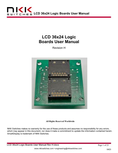
This document provides detailed instructions for using NKK's LCD 36x24 Logic Boards, including how to connect them via daisy-chain ribbon cables and control switches using microcontroller pins. It covers board dimensions, pin functions, switch numbering, and backlight control. Schematics and key terms are also included for technical reference.
The manual includes part numbers for various board configurations and a signal booster for extended daisy-chains. It warns against improper connections and includes a limited one-year warranty against manufacturing defects.
Logic boards are switch panels that have glue logic to convert addressing and switch scanning to serial.
The Vsup pin requires 7V to 12V.
The switch scans should be more than 10ms apart to prevent de-bouncing reads.