
This manual introduces the installation and operation of VCM inverters.
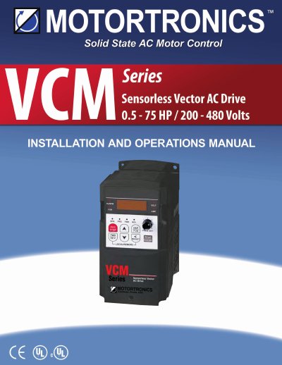
This manual provides step-by-step instructions for installing and operating Motortronics VCM inverters, covering product inspection, safety precautions, wiring diagrams, terminal configurations, control modes, and troubleshooting. It includes detailed sections on power and control terminal wiring, parameter settings, error codes, and periodic inspections. Safety warnings are emphasized throughout to prevent injury or equipment damage.
The manual supports both basic and advanced parameter configurations, allowing flexible control for various applications. It also includes diagrams for mounting, grounding, and connecting peripheral devices, as well as troubleshooting flowcharts for common faults such as motor overheating or instability.
| Display | 3-digit 7-segment display |
|---|---|
| Communication Protocol | MODBUS RTU |
Connect the motor terminals T1 (U), T2 (V), and T3 (W) to the output terminals, not the input terminals.
The inverter accepts an input voltage of AC x phase 50/60 Hz with a tolerance of +10% and -15%.
Adequate ventilation must be provided to keep the temperature below 40 °C (104°F) to prevent overheating or fire.
If the power loss is greater than 2 seconds, the inverter cannot sustain power to the control circuit.