
This document describes the wiring pin connections for the Digi-Max D1000 controller harness
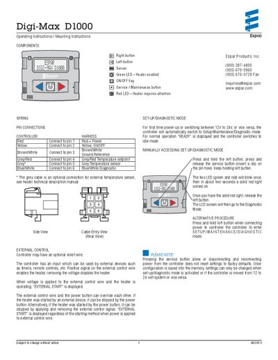
The manual details the wiring harness for the Digi-Max D1000 controller, including pin assignments for power, ground, temperature setpoint, sensor, diagnostic, and optional external control connections. It also describes the external control wire function and LED indicators for heater status.
The document explains how to access Setup/Diagnostic mode, adjust voltage thresholds, runtime limits, temperature display units, and handle fault conditions. Test mode procedures, LED behavior, and a drilling template for mounting are also included.
| System voltage | 12 V or 24 V (auto‑detect) |
|---|---|
| Under‑voltage shutdown threshold | 11.4 V (default) |
| Maximum runtime | 10 hrs (default) |
| Runtime range | 1‑24 hrs (outside becomes UNLIMITED) |
| Temperature display units | Fahrenheit (default) or Celsius |
| Green LED indication | Heater enabled |
| Red LED indication | Heater requires attention (e.g., undervoltage) |
The red LED shows that the heater requires attention, such as an undervoltage condition; after 5 minutes of undervoltage the red LED turns on and a warning is displayed.