
SiP32419EVB and SiP32429EVB are a load switch from Vishay Siliconix that integrates multiple control features to simplify the design and increase the reliability of the circuitry connected to the switch. The switch is designed to operate in the 6 V to 28 V range and features a 56 mΩ RON. An internally generated gate drive voltage ensures good RON linearity over the input voltage operating range. The switch also has a slew rate control circuit that controls the switch turn-on time to the value set by an external capacitor. After soft start, an over-current protection circuit (OCP) continuously monitors the current through the load switch, and controls the switch impedance to limit the current to the level programmed by an external resistor. If the over-current condition persists for more than 7 ms, the switch shuts off automatically. The switch also has an over temperature protection circuit (OTP) that will shut the switch off if the junction temperature exceeds about 145 °C. The OTP circuit will release the switch when the temperature has decreased by about 20 °C.
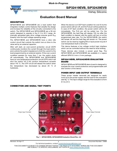
The document provides an evaluation board manual for the SiP32419EVB and SiP32429EVB load switches. These devices integrate multiple control features, including over-current protection (OCP) and programmable soft-start, to simplify circuit design and increase reliability. The evaluation board is designed to demonstrate these specific functions.
| Switch Resistance | 56 mΩ |
|---|---|
| Operating Voltage Range | 6 V to 28 V |
| Package Type | DFN10 3 mm x 3 mm |
| Input Voltage Range (Board) | 6 V to 24 V |
| Capacitor Voltage Rating | 50 V |
| Enable Pin Voltage Rating | 6 V |
| Enable Threshold Voltage | 1.5 V |
| Disable Threshold Voltage | 0.4 V |
| Over-Current Trip Time | 7 ms |
| Over-Temperature Trip Temperature | 145 °C |
| Measured Current Limit | 1.365 A |
The devices are designed to operate in the 6 V to 28 V range.
The circuit monitors current and shuts off the switch automatically if the over-current condition persists for more than 7 ms.
The power switch turns off immediately, and the FLG pin is pulled low.
The limit is calculated using the formula ILIM = 1.24 V x 5000 / RSET, where RSET is the current limit resistor.