
This document introduces the safety information, system components, system design, piping, mounting the controller, power supply and wiring, starting the system, application switches, motor rotation, diagrams, motor overload, switch settings, troubleshooting, controller dimensions and limited warranty of the AquaBoost II controller.
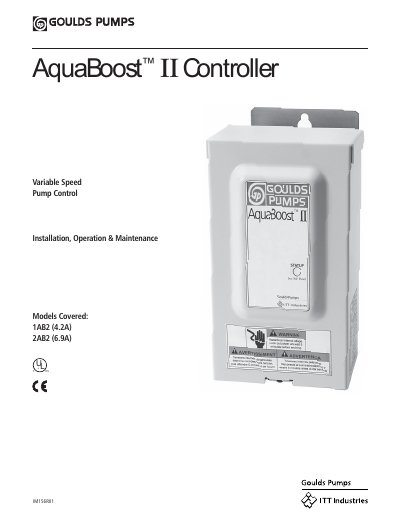
The document provides comprehensive instructions for installing and operating the AquaBoost II Controller, a variable speed pump control system. It details system components including the controller, pressure tank, and sensor, along with specific requirements for plumbing connections and electrical wiring to ensure safe operation.
Key operational guidance includes setting amp limits and pressure settings, configuring application switches, and understanding motor rotation. The manual also addresses troubleshooting common issues, provides physical dimensions of the unit, and outlines warranty terms.
| Models Covered | 1AB2 (4.2A), 2AB2 (6.9A) |
|---|---|
| Pressure Sensor Cable Length | 80 inches |
| Ambient Temperature Range | 34° F (1.1° C) to 104° F (40° C) |
| Tank Pre-charge Standard | 18 PSI |
Installation and maintenance MUST be performed by properly trained and qualified personnel.
No, galvanized fittings or pipe should never be connected directly to the stainless steel discharge head as galvanic corrosion may occur.
The maximum working pressure of the V6P tank is 125 psi.