
This document is the operation manual for ELCO Power Factor Controller PFR5ELCO0006 / PFR5ELCO0014. The manual covers the controller's interface, installation and connection, operation modes, numeric display, LED indications, parameter setup, and alarm trigger setting.
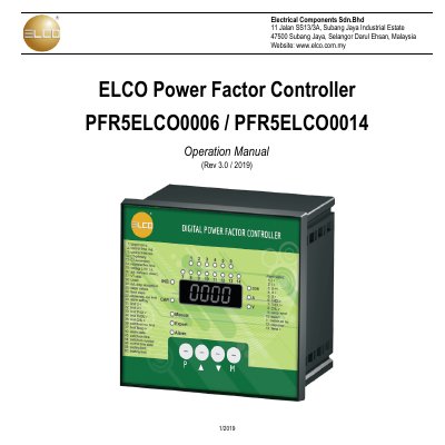
The document serves as an operation manual for the ELCO PFR5 series of power factor controllers. It details the controller interface, installation procedures including wiring connections, and explains the startup process involving automatic configuration detection and step power recognition.
The guide provides comprehensive instructions on operating the device in both automatic and manual modes, configuring parameters via the numeric display, interpreting LED indications, and setting alarm triggers. It also includes a full list of technical specifications for the PFR5ELCO0006 (6 steps) and PFR5ELCO0014 (14 steps) models.
| Number of Output Relays (PFR5ELCO0006) | 6 |
|---|---|
| Number of Output Relays (PFR5ELCO0014) | 14 |
| Power Supply Range | 90 - 275 VAC; 43 – 67 Hz |
| Voltage Measurement Accuracy | +/-1% Of Range, +/- 1 Digit |
| Operating Temperature | -40° - +60°C |
To determine the voltage measurement phase connection and nominal voltage by taking one set of measurements when steps 1~4 are connected and disconnected consecutively.
The process takes three sets of measurements to determine the reactive power value.
The controller supports a maximum cable size of 2.5 mm².