
The DIN-68M-J3A is used for wiring between Mitsubishi J3A series servo drivers / stepper with pulse trains input driver and ADLINK cPCI-8168, PCI-8102 motion controller card ONLY. It provides 2 connection methods: CNIF1 & CNIF2 connectors for Mitsubishi J3A series servo drivers, and a SJ connector for stepping drivers. DO NOT use both connectors at the same time.
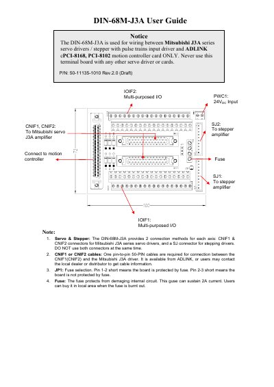
The ADLINK DIN-68M-J3A is a motion control terminal board designed to provide interface connections between Mitsubishi J3A series servo drivers or stepping drivers and specific ADLINK motion controller cards, namely the cPCI-8168 and PCI-8102. The device supports two distinct connection methods for each axis: CNIF1/CNIF2 connectors for Mitsubishi J3A series servo drivers and a single SJ connector for stepping drivers; users must not use both connector types simultaneously.
| Supported Motion Controller Cards | cPCI-8168, PCI-8102 |
|---|---|
| Fuse Current Rating | 2A |
| External Power Input Voltage | +24V DC ± 5% |
No, you must not use both connector types simultaneously for each axis.
One pin-to-pin 50-PIN cable is required for this connection.
Short pins 1-2 on JP1 to enable fuse protection.