
The DIN-814M-J3A is a user guide that provides information on the connection methods, signal definitions, and pin assignments of the product.
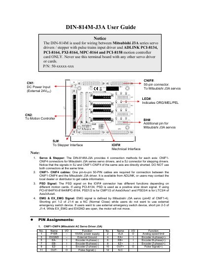
The ADLINK DIN-814M-J3A is a motion controller interface board designed to provide connection methods for Mitsubishi J3A series servo drivers and stepping drivers. It supports four connection methods per axis via CNIF1-CNIF4 connectors for Mitsubishi J3A series and an SJ connector for stepping drivers. Users must ensure that signals in the SJ and CNIF1-CNIF4 connectors of the same axis are not used simultaneously as they are directly shorted.
The manual provides detailed pin assignments for various connectors including CNIF1-CNIF4, IOIF#, SJ#, BH#, and CN1. It explains signal functions such as EMG, PSD, and ALM, and details the mechanical dimensions of the board. Specific wiring instructions are provided for external power inputs, jumper settings for emergency stop signals, and connections to motion controller cards like PCI-8134, PCI-8164, PXI-8164, MPC-8164, and PCI-8158.
| Compatible Motion Cards | PCI-8134, PCI-8164, PXI-8164, MPC-8164, PCI-8158 |
|---|---|
| External Power Supply Input | +24V DC ± 5% |
| Connector Type for Mitsubishi J3A | 50-pin connector |
No, the signals in SJ and CNIF1-CNIF4 of the same axis are directly shorted, so you must not use both connectors at the same time.
The function depends on the motion card; for PCI-8134 it is a positive slow down signal, while for PCI-8164/PXI-8164/MPC-8164 it is used for CMP or LTC signals.
You can select the source by setting the jumper: position 1 is EXGND, position 2 is EMG, and position 3 is EX_EMG.