
The STC4054 is a constant current/constant voltage charger for single cell Li-Ion batteries. No external sense resistor or blocking diode is required and its ThinSOT package make it ideally suited for portable applications. The STC4054 is designed to work within USB power specifications. An internal block regulates the current when the junction temperature increases, in order to protect the device when it operates in high power or high ambient temperature. The charge voltage is fixed at 4.2V, and the charge current limitation can be programmed using a single resistor connected between PROG pin and GND. The charge cycle is automatically terminated when
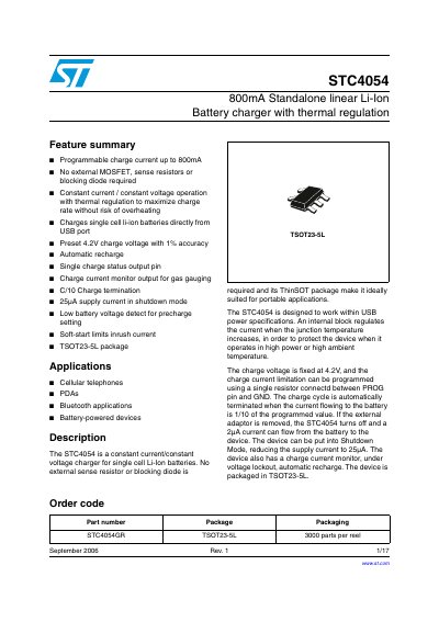
The STC4054 is a constant current/constant voltage charger designed for single-cell Li-ion batteries. It operates directly from a USB port and requires no external MOSFET, sense resistors, or blocking diode. The device features a fixed 4.2V charge voltage and programmable charge current up to 800mA via a single resistor.
| Charge current | up to 800 mA |
|---|---|
| Charge voltage | 4.2 V |
| Input supply voltage | 4.25 V to 6.5 V |
| Package | TSOT23-5L |
| Max junction temperature | 125 °C |
No external MOSFET, sense resistors, or blocking diode are required.
The supply current in shutdown mode is 25 µA.
The charge current is programmed using a single resistor connected between the PROG pin and GND.