
This application note presents an example of the use of the HALT mode. In this application, the MCU (here a ST72251) is waked up by an external interrupt caused by someone pressed a key on the 4x4 matrixed keypad.
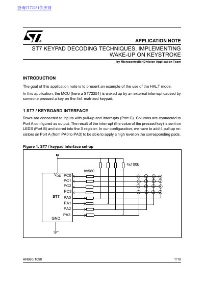
The document presents an example application where the ST72251 microcontroller is woken up from HALT mode by an external interrupt triggered by a key press on a 4x4 matrix keypad. The MCU decodes the pressed key and outputs the result on LEDs before returning to the low-power state.
The note details the hardware configuration, including connecting rows to Port C (inputs with pull-up and interrupts) and columns to Port A (outputs). It also provides the specific assembly code required to initialize the ports, manage the HALT mode, and execute the key decoding algorithm.
| Microcontroller Model | ST72251 |
|---|---|
| Keypad Type | 4x4 matrixed keypad |
| Wake-up Trigger | External interrupt caused by key press |
| Power Mode | HALT mode |
| Row Configuration | Inputs with pull-up and interrupts |
| Column Configuration | Port A configured as output |
| Interrupt Edge | Falling edge only |
| Minimum Key Press Duration | 0.5 to 1 second |
The MCU is woken up by an external interrupt caused by a key press on the keypad.
The microcontroller enters HALT mode, which is its lowest power consumption mode.
Rows are connected to Port C as inputs with pull-up and interrupts, while columns are connected to Port A as outputs.