
The TD352 is ST's latest generation of IGBT/MOSFET gate driver, with 1.7A sink current and 1.3A source current. It features active Miller clamp function, desaturation detection, adjustable turn-on delay, UVLO protection and 2kV ESD protection. It is suitable for 1200V three-phase inverters, motor control systems and UPS applications.
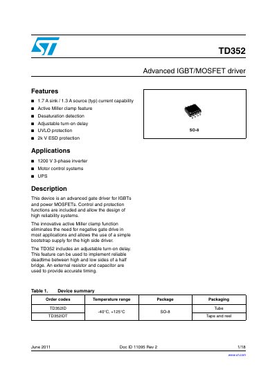
The TD352 is a high-reliability gate driver designed for 1200 V three-phase inverters, motor control systems, and UPS applications. It supports both IGBTs and power MOSFETs with key features including active Miller clamp to eliminate the need for negative gate drive, desaturation detection for fault protection, and an adjustable turn-on delay.
The device operates from a single positive supply voltage (UVLO to 26 V) and includes undervoltage lockout (UVLO) protection. It is available in a SO-8 package with operating temperatures ranging from -40°C to +125°C.
| Output sink current (typ) | 1.7 A |
|---|---|
| Output source current (typ) | 1.3 A |
| Maximum supply voltage | 28 V |
| Operating temperature range | -40 to +125 °C |
| Package type | SO-8 |
The device is designed for 1200 V three-phase inverters, motor control systems, and UPS.
No, the active Miller clamp feature eliminates the need for negative gate drive in most applications.
Turn-on delay is programmable through an external resistor (Rg) and capacitor (Cg).