
L4954 is a quad output voltage regulator and a three output high side driver. The IC includes monitoring circuitry to warn the microprocessor of a low voltage condition: the LVWarn, output, sensing the slow dropping of STCAP pins voltage, gives the microprocessor time to store data. A reset output is generated at REG4’s decay. External protection must be provided for reverse battery protection.
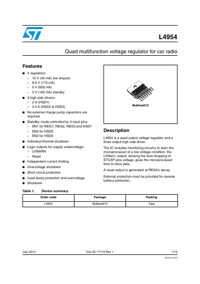
The L4954 is an integrated circuit featuring four independent voltage regulators with different output voltages (10V, 8.5V, 5V) and currents, plus three high-side drivers. It includes logic outputs for supply undervoltage monitoring (LVWarn) and a reset signal to warn microprocessors of low voltage conditions.
The device operates without external charge pump capacitors and offers individual thermal shutdown protection. Standby modes are controlled by specific input pins (EN1, EN2, ENS), allowing the chip to reduce power consumption when not in active use.
| Operating supply voltage (Vg) | 11 to 16 V |
|---|---|
| Regulator 1 output voltage | 10 V at 40 mA |
| Regulator 2 output voltage | 8.5 V at 175 mA |
| Regulator 3 output voltage | 5 V at 650 mA |
| High side driver 1 current | 2 A |
| High side drivers 2 & 3 current | 0.3 A |
| Operating temperature range | -40 to 85 °C |
No, no external charge pump capacitors are required for this device.
The LVWarn output warns a microprocessor of a low voltage condition by sensing the slow dropping of supply voltage.
Standby mode is controlled by input pins EN1 (for REG1-3 and HSD1), EN2 (for HSD2), and ENS (for HSD3).