
This manual describes the overview, structure, installation and operation of the INTERBUS UFI11A fieldbus interface.
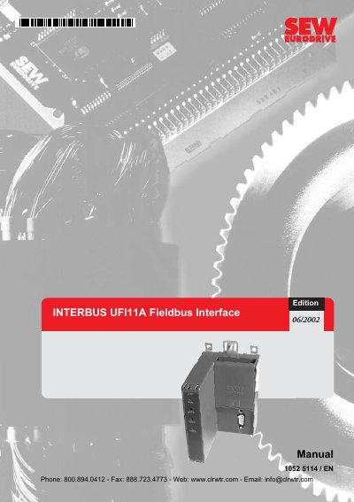
The UFI11A serves as a gateway to connect one or more MOVIDRIVE, MOVIDRIVEcompact, or MOVITRAC 07 inverters to an INTERBUS system. It translates between the INTERBUS protocol and the SBus protocol, allowing multiple inverters to be connected via the SBus interface.
The document provides detailed instructions on physical installation, including DIN rail mounting and grounding requirements. It also covers configuration procedures using Autosetup mode, PC connections, DIP switch settings, and explains the function of diagnostic LEDs and error codes.
| Connector type (Incoming) | 9-pin sub D male |
|---|---|
| Connector type (Outgoing) | 9-pin sub D female |
| Conductor cross section | 0.75 mm2 (AWG18) |
The UFI11A can connect MOVIDRIVE, MOVIDRIVEcompact, or MOVITRAC 07 inverters to INTERBUS.
Yes, several inverters can be connected to the UFI11A interface via the SBus.