
The document introduces the installation method of SAFETY 300-BT SERIES 12 products, including installation location and installation method
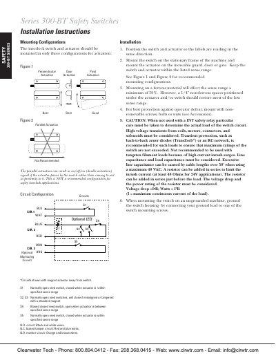
This document provides installation instructions for the Clearwater Tech 300-BT Series GuardSwitch. It details recommended mounting configurations, such as perpendicular door pivots versus parallel actuation, and explains how to mount the switch on stationary frames while keeping the actuator on moveable guards or gates.
The guide includes specific wiring diagrams for Category 3 and Category 4 safety circuits using INT series safety monitor relays. It specifies fuse requirements (e.g., 1A for 230V AC, 80mA for 120V AC), maximum guard counts per circuit, and necessary transient protection measures like back-to-back zener diodes or RC networks to prevent damage from high voltage transients.
| Humidity Rating | 30 to 95% |
|---|---|
| Environment Pollution Degree | II |
| Fuse Requirement (120V AC) | 80mA |
Transient protection, such as back-to-back zener diodes (TransZorb*) or an RC network, is recommended to ensure maximum ratings are not exceeded.
Ground the switch housing by connecting your ground lead to one of the switch mounting screws.