
The document describes a 3A step-down switching regulator demonstration board based on L5987, L5987A, featuring adjustable output voltage, programmable switching frequency, overcurrent and thermal protection.
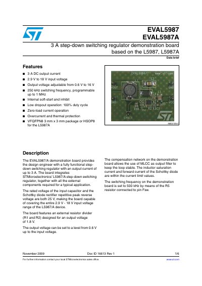
The document describes the EVAL5987 and EVAL5987A demonstration boards, which are based on the L5987 and L5987A step-down switching regulators. These boards provide a fully functional design for engineers with an output current of up to 3 A.
| Output current | 3 A |
|---|---|
| Input voltage range | 2.9 V to 18 V |
| Output voltage range | 0.6 V to 16 V |
| Switching frequency | 250 kHz to 1 MHz (programmable) |
| Package type | VFQFPN8 or HSOP8 |
The demonstration board provides a fully functional step-down switching regulator with an output current of up to 3 A.
The board features an external resistor divider designed for an output voltage of 1.8 V.
The switching frequency is set to 500 kHz by means of the R5 resistor connected to pin Fsw.