
The STEVAL-ISQ009V1 demonstration board is composed of three identical sections (daughterboards) and a motherboard. Each daughterboard is capable of performing DC-DC conversion starting from +5 VDC and is designed to deliver 3.3 V / 5 A to the load. The input terminals of the motherboard are connected to a +5 VDC external source and the output terminals to the load. The board can accommodate up to three DC-DC converters. The motherboard contains the circuitry necessary to perform current sharing (utilizing the L6615) and to isolate a failed section from the load. It is designed to be adaptable to all power supplies (compatible with the L6615 absolute maximum ratings) having remote sense pins. By changing just a few components, it can be modified for new specifications. It is possible to build a system to supply a 10 A load at +3.3 V in a 2+1 redundant configuration. That is, whenever three sections are running, each of them supplies 3.33 A, a value lower than its no
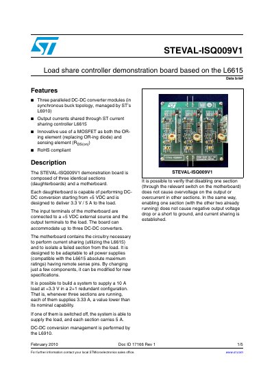
The STEVAL-ISQO09V1 is a demonstration board composed of three identical daughterboards and a motherboard. Each daughterboard performs synchronous buck topology DC-DC conversion, delivering 3.3 V at 5 A from a +5 VDC input source.
The motherboard manages the system by utilizing the L6615 current sharing controller to distribute output currents across the modules. It also includes circuitry to isolate failed sections and supports configurations up to three converters for high-current applications.
Each daughterboard is designed to deliver 3.3 V at 5 A to the load.
It is possible to build a system to supply a 10 A load at +3.3 V.
If one section is switched off, each remaining section carries 5 A.