
The 74F114 is a dual JK negative edge-triggered flip-flop with common Clock and Clear inputs, manufactured by Fairchild Semiconductor Corporation. The product supports synchronous state changes.
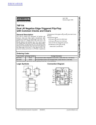
This document is a technical datasheet for the Fairchild Semiconductor 74F114, which contains two high-speed JK flip-flops featuring common Clock and Clear inputs. Synchronous state changes are initiated by the falling edge of the clock, while asynchronous set and clear functions allow independent control of outputs regardless of the clock signal.
The datasheet provides comprehensive electrical characteristics for both DC and AC operating conditions at supply voltages of +5.0V and +8.0V. It includes absolute maximum ratings, logic symbols, connection diagrams, truth tables, and physical dimensions for available packages: the 14-Lead Small Outline Integrated Circuit (SOIC) and the 14-Lead Plastic Dual-In-Line Package (PDIP).
| Supply Voltage (Recommended) | +4.5V to +5.5V |
|---|---|
| Operating Temperature Range | 0°C to +70°C |
| Maximum Clock Frequency (at Vcc=+8.0V) | 75 MHz |
| Setup Time (HIGH or LOW) | 4.0 ns Min |
A LOW signal on Sp prevents clocking and forces Q to a HIGH level, while a LOW signal on Cp forces Q to a LOW level.
Synchronous state changes are initiated by the falling edge of the clock, and triggering occurs at a voltage level not directly related to transition time.
Simultaneous LOW signals on Sb and Cp force both Q and Q to a HIGH level.