
This document introduces an application of a high power factor flyback LED driver based on the L6562A and TSM101 controllers. The driver uses isolated feedback with an optocoupler and a secondary side reference/error amplifier, the TSM101, for voltage and current regulation. The L6562A is a PFC controller operating in transition-mode, with a highly linear multiplier that reduces AC input current distortion and allows wide-range mains operation with extremely low THD. The TSM101 compares the DC voltage and current level of a switching power supply to an internal reference, providing feedback to the L6562A controller. This system, designed using the L6562A and TSM101 controllers, offers advantages in terms of output current and voltage stability.
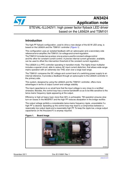
The document details a high-power-factor (PF) flyback configuration designed to drive a 60 W LED array. The system utilizes an isolated feedback loop with an optocoupler connecting the secondary side controller, TSM101, to the primary side PFC controller, L6562A.
The design achieves high efficiency, exceeding 90% at heavy loads, by employing transition-mode operation for the MOSFET and a high power factor that reduces dissipation in the bridge rectifier. The text provides step-by-step design calculations, electrical schematics, bill of materials, thermal measurement data, and EMC test results.
| Output Power | 60 W |
|---|---|
| Mains Voltage Range | 185 Vac to 265 Vac |
| Minimum Mains Frequency | 47 Hz |
| DC Output Voltage | 130 V |
| Maximum Output Current | 0.462 A |
| Expected Efficiency | 92% |
The design is based on the L6562A PFC controller and the TSM101 voltage and current controller.
The design specifies a maximum 2fL output ripple of 1.0%.