
This application note describes the electronic lamp ballast for 70 W high intensity discharge (HID) metal halide lamps (MHL) used for general indoor applications. The ballast is composed of a boost converter and an inverter. The inverter is realized by a full bridge driver with a power control circuit. The booster converter for power factor correction (PFC) is controlled by the L6562A controller (U1). The inverter is a full bridge topology driven by two pairs of half bridge buck converters, L6385E (U3) and L6569 (U4), with the constant power control circuit L6562A (U2). In this note the dual-buck converter is introduced. One works in high frequency and the other works in complementarity with necessary dead time at a lower frequency.
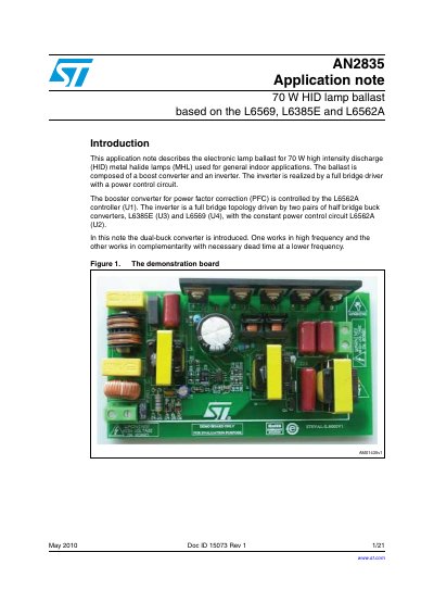
This document details an electronic ballast for 70 W high intensity discharge (HID) metal halide lamps used in general indoor applications. The design utilizes a boost converter for power factor correction and a full bridge inverter topology. The inverter is realized using two pairs of half bridge buck converters, specifically the L6385E and L6569, driven by the L6562A controller.
| Lamp Type | 70 W high intensity discharge (HID) metal halide lamps |
|---|---|
| Application | general indoor applications |
| Controller Components | L6569, L6385E and L6562A |
| Topology | boost converter and an inverter |
| Inverter Type | full bridge driver with a power control circuit |
The demonstration board is designed for demonstration purposes only and must not be used for domestic or industrial installations.
The power control circuit provides constant current control during warm-up and constant power control during steady-state operation.