
This document mainly introduces the calibration registers of AD7739, including two register sets. The first register set includes 24-bit offset register and 24-bit gain register, which affect all channels. The second register set includes per channel 24-bit offset register and a 24-bit per channel gain register, which affect a specific channel only.
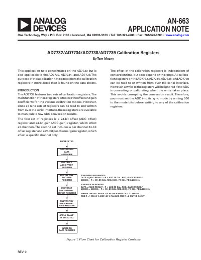
This document explains how to manipulate raw ADC conversion results by reading from and writing to the shared 24-bit offset and gain registers. It details the impact of these registers on all channels versus per-channel specific adjustments.
The note provides instructions for implementing a digital Programmable Gain Amplifier (PGA) using the per-channel gain coefficient, allowing users to achieve input ranges smaller than the lowest available analog range (+0.625 V). It includes mathematical methods and examples for picking coefficients to give a specific gain.
| Supported Devices | AD7732, AD7734, AD7738, AD7739 |
|---|---|
| Offset Register Size | 24-bit |
| Gain Register Size | 24-bit |
| Default Offset Value | 0x800000 |
| Default Gain Value | Gain of 1 (0x800000) |
| Per Channel Gain Range | 0 to 8 |
You must set the ADC into its sync mode by writing 000 to the mode bits before writing to any of the calibration registers.
Increasing the offset register contents increases or decreases the output of all future conversions on that specific channel, depending on the sign bit.
You can use the per-channel gain coefficient to multiply outputs, allowing for input ranges smaller than the lowest available analog range (e.g., +0.625 V).