
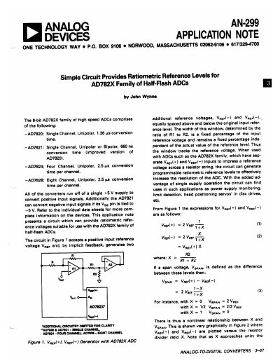
The document presents a circuit design that generates two additional reference voltages, Vref(+) and Vref(-), equally spaced above and below an input reference level. This window tracks the reference voltage independently of its actual value, allowing for programmable ratiometric reference levels suitable for the AD782X family of half-flash ADCs.
The note details how to use resistor dividers or digital-to-analog converters (DACs) to create a variable divider ratio X. This technique effectively increases the ADC's resolution in 6 dB steps, monitors input voltage tolerances as a percentage of nominal value, and handles both positive and negative reference voltages using specific configurations for the AD7821.
| Supported Devices | AD7820, AD7821, AD7824, AD7828 |
|---|---|
| Supply Voltage | +5 V |
| AD7820 Conversion Time | 1.36 µs |
| AD7821 Conversion Time | 660 ns |
| AD7824 Channels | Four Channel |
| AD7828 Channels | Eight Channel |
By generating additional reference voltages spaced above and below the input level, it increases effective resolution in 6 dB steps using specific resistor divider ratios.
Only the AD7821 can directly convert negative voltages by tying its Vsg pin to -5 V.
The document suggests using discrete resistors with switches or an 8-bit DAC like the AD7524.