
This document is provided by ICminer.com Electronic-Library Service. The service is copyrighted in 2003. The document describes the features and characteristics of ICminer.com Electronic-Library Service.
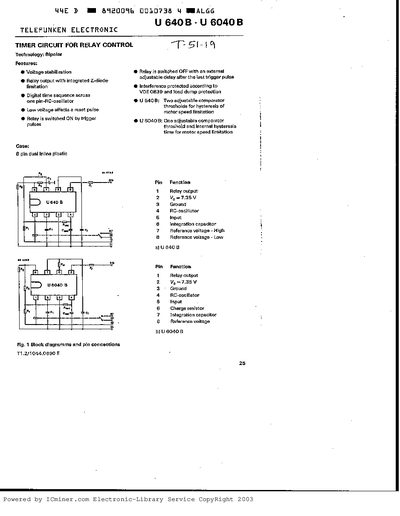
This document describes the Telefunken U 640B and U 6040B integrated circuits, which are bipolar timer circuits used for relay control applications. Key features include voltage stabilization, a digital time sequence generated by a one-pin RC-oscillator, and an interference-protected relay output with an integrated Z-diode to limit inductive switch-off voltages.
| Technology | Bipolar |
|---|---|
| Case type | 8 pin dual inline plastic |
| Relay output pulse current | 1.5 A |
| Oscillator maximum frequency | 20 kHz |
| Upper switching point (approx) | 4.9 V |
| Lower switching point (approx) | 1.8 V |
The Z-diode limits the relay winding's inductive switch-off voltage to prevent destruction of the output transistor.
The absolute maximum rating for the supply voltage at terminal KI15 is 15 V.
The relay output is designed for a pulse current of approximately 1.5 A.