
Agilent Technologies I/O Connector PWA Installation Instructions

This file is the installation instructions for the I/O connector of Agilent 7890 GC.
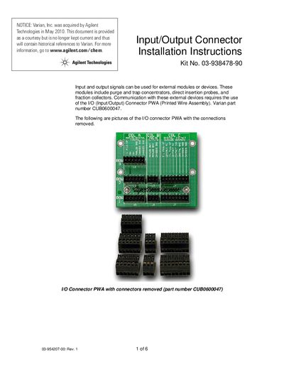

Agilent Technologies I/O Connector PWA Installation Instructions - cover page
Brand
Agilent
Document type
Installation Guide
Language
English
Pages
6
File format
PDF
File size
366 KB
Published
07 June, 2012
Updated
01 October, 2023
MD5 checksum
AEBB29FB253B751669EC977656A82ED5

About this manual

This guide provides installation instructions for the Input/Output (I/O) Connector Printed Wire Assembly (PWA), part number CUB0600047. The document explains how to wire external devices such as purge and trap concentrators, direct insertion probes, and fraction collectors using Start-In, Ready-In, and signal output configurations.

What's inside

  • Hardware Setup
  • Start In Signal Wiring
  • Ready In Signal Wiring
  • Software Setup
  • Connection to Instrument

Frequently asked questions

What is the maximum current rating for the Start Out and Ready Out signals?

The maximum current allowed for these output signals is 100 mA.

Which specific part number is used for the I/O Connector PWA?

The required Printed Wire Assembly has the part number CUB0600047.

Download PDF (366 KB)

More Agilent Manuals


View all Agilent manuals →