
This document introduces a high linearity direct conversion receiver design method that uses high performance analog integrated circuits to achieve high linearity, low noise and good I-Q channel matching.
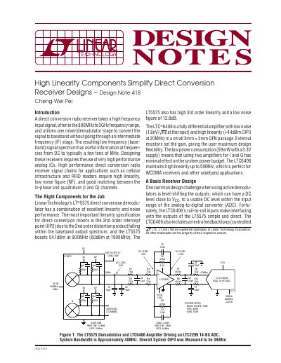
This document describes a design for a high linearity direct conversion radio receiver system. The primary components include the LT5575 direct conversion demodulator and the LTC6406 fully differential amplifier driving an LTC2299 14-bit ADC. The system achieves a bandwidth of approximately 40MHz with an overall OIP3 measured at 39dBm.
| System Bandwidth | Approximately 40MHz |
|---|---|
| Overall System OIP3 (Basic) | 39dBm |
| LT5575 IIP2 at 900MHz | 54.1dBm |
| LT5575 Noise Figure | 12.8dB |
| LTC6406 Input Noise | 1.6nV/√Hz at the input |
| LTC6406 OIP3 | +44dBm OIP3 at 20MHz |
| LTC6406 Power Consumption | 59mW with a 3.3V supply |
| System OIP3 (Enhanced) | 45dBm at 920MHz RF |
| System Noise Figure (Enhanced) | 19dB |
It takes a high frequency input signal and utilizes one mixer/demodulator stage to convert the signal to baseband without going through an intermediate frequency (IF) stage.
The LT5575 boasts a 2nd order intercept point of 54.1dBm at 900MHz.
The LTC6406 has an input noise figure of 12.8dB.