
This document provides specifications and dimensions for different models of resistors, as well as their features and characteristics. This includes working voltage, power derating curve, rated voltage, resistance range, and packaging options.
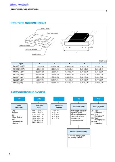
The document details the physical dimensions, electrical specifications, and tolerance coding for a range of thick‑film chip resistors (RC1005, RC1608, RC2012, RC3216, RC3225, RC5025, RC6432). It includes power rating curves, working and overload voltage limits, resistance ranges, and temperature coefficients for each series.
Packaging information covers carrier‑tape formats, reel sizes (7‑inch, 10‑inch, 13‑inch) and standard quantities, as well as bulk bag packaging. The data is intended for designers and manufacturers needing precise component specifications for SMD assembly and automatic placement processes.
| Power Rating (W) at 70°C for RC1005 | 0.063W |
|---|---|
| Working Voltage (Max) for RC1005 | 50V |
| Overload Voltage (Max) for RC1005 | 100V |
| Resistance Range for D tolerance | 10~1M Ω |
| Temperature Coefficient for D tolerance | +800/200 PPM/°C |
| Standard 7‑inch reel quantity | 5,000 EA per reel |
Tolerances are shown using a 3‑ or 4‑digit IEC coding system, where the first digits represent the resistance value and the last digit indicates the tolerance code.