
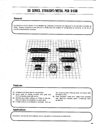
The handbook describes the SD series straight/metal PCB D‑Sub connectors, which mount vertically on printed circuit boards and are used in computers, peripherals, control equipment, and measuring instruments. It lists the available contact configurations (9, 15, 25, 37, and 50 contacts) and highlights the compact, sturdy metal shell and gold‑plated contacts.
Technical data such as current rating, voltage rating, insulation resistance, and material finishes are given, together with recommended mounting hole patterns and part numbers for each model. The document is intended for designers and engineers selecting the appropriate connector for their PCB designs.
| Current rating | 3 A |
|---|---|
| Insulation resistance | 5000 MΩ or more |
| Contact resistance | 15 mΩ or less |
| Shell material | Steel, nickel‑plated |
| Insulator material | PBT (GE Valox) |
| Contact material | Phosphor bronze (Selective Gold/Nickel) |
They are rated for a 3 A current and AC 50 V voltage.
The series offers 9, 15, 25, 37, and 50‑contact models.
The shell is steel with nickel plating, and the contacts are phosphor bronze with optional gold or nickel plating.