
LTC1645 1645fa Dual-Channel Hot Swap Controller/Power Sequencer
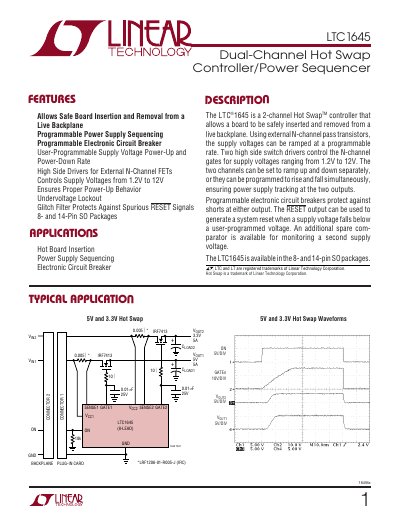
The LTC1645 is a dual‑channel hot‑swap controller that enables safe insertion and removal of boards on a live backplane. It uses external N‑channel pass transistors to ramp supply voltages from 1.2 V to 12 V with programmable rates, provides electronic circuit‑breaker protection, and generates a RESET output for system reset.
The document includes electrical characteristics, pin descriptions, typical performance curves, application notes on power‑supply tracking and sequencing, and guidance on selecting external N‑channel MOSFETs. Package options are 8‑lead and 14‑lead SO, and the device operates from –40 °C to 85 °C (industrial grade).
| Supply Voltage Range | 1.2 V to 12 V |
|---|---|
| Operating Temperature Range | -40 °C to 85 °C |
| Undervoltage Lockout VLK O1 (typical) | 2.23 V |
The RESET pin is pulled low when the voltage at the FB pin falls below 1.238 V or VCC1 drops below its undervoltage lockout threshold, and goes high after the voltage recovers.
The TIMER pin requires an external capacitor to ground to create a timing delay; when inactive an internal N‑channel FET shorts the pin to ground, and when active it sources a 2 mA current to ramp the voltage.
GATE1 and GATE2 drive external N‑channel MOSFETs; an internal charge pump guarantees at least 4.5 V of gate drive for each channel.