
TL�F�9553 54F�74F540 � 54F�74F541 is an octal buffer-line driver with TRI-STATE outputs. They are similar in function to the 'F240 and 'F244, except that the inputs and outputs are on opposite sides of the package, making them especially useful as output ports for microprocessors, allowing ease of layout and greater PC board density.
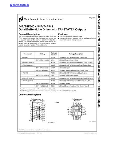
The 54F/74F540 and 54F/74F541 octal buffer/line driver devices feature TRI‑STATE outputs that can drive bus lines and present a high‑impedance state, making them suitable for microprocessor interface applications. The pinout places inputs and outputs on opposite sides of the package, simplifying board layout and increasing density.
The handbook includes detailed package options, connection diagrams, absolute maximum ratings, recommended operating conditions, and both DC and AC electrical characteristics. It also provides ordering information, physical dimensions for each package type, and a life‑support policy notice.
| Input HIGH Voltage (VIH) | 2.0 V |
|---|---|
| Input LOW Voltage (VIL) | 0.8 V |
| Output LOW Voltage (VOL) typical | 0.55 V |
| Power Supply Current (Icc) for 54F | 20 mA (typical) |
| Propagation Delay (tPHL) typical | 3.0 ns |
| Commercial Temperature Range | 0 °C to +70 °C |
The TRI‑STATE outputs can drive bus lines and also present a high‑impedance state (Z) when disabled.
The input voltage may range from –0.5 V to +7.0 V.
Available packages include 20‑lead molded dual‑in‑line (N20A), ceramic dual‑in‑line (J20A), molded small outline (M20B), and ceramic leadless chip carrier (E20A), among others.