
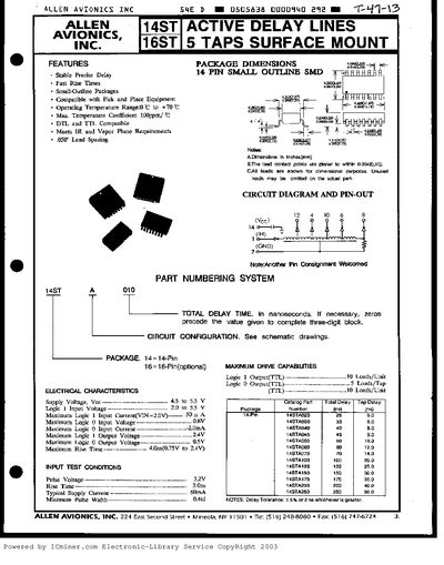
The Allen Avionics Active Delay Lines are available in 14‑pin and optional 16‑pin small‑outline packages. They provide stable, precise delay times, fast rise times, and are compatible with pick‑and‑place equipment. The devices meet IR and vapor‑phase requirements and feature a temperature coefficient of 100 ppm/°C.
Electrical characteristics include a supply voltage of 45‑55 V, logic‑1 input voltage of 2.0‑5.5 V, and maximum rise times up to 100 ns. Detailed pin‑out diagrams and part‑numbering information are provided for both the 14‑pin and 16‑pin configurations.
| Package | 14‑Pin Small Outline SMD (optional 16‑Pin) |
|---|---|
| Pin Count | 14 pins (optional 16‑pin version) |
| Operating Temperature Range | 0 °C to +70 °C |
| Temperature Coefficient | 100 ppm/°C |
| Supply Voltage | 45 V to 55 V |
| Logic 1 Input Voltage | 2.0 V to 5.5 V |
| Maximum Rise Time | 100 ns |
The device operates from 0 °C up to +70 °C.
It requires a supply voltage between 45 V and 55 V.
Logic 1 input voltage is specified as 2.0 V to 5.5 V.
The 14ST version has 14 pins; a 16‑pin version is also available.