
This document introduces the LT1616 600mA, 1.4MHz step-down switching regulator, which uses an internal 0.6A power switch and is packaged in a tiny 6-lead SOT-23. The wide input range of 3.6V to 25V makes the LT1616 suitable for regulating a wide variety of power sources, from 4-cell batteries and 5V logic rails to unregulated wall transformers and lead-acid batteries. Its high operating frequency allows the use of tiny, low cost inductors and ceramic capacitors. With its internal compensation eliminating additional components, a complete 400mA step-down regulator fits onto 0.15 square inches of PC board area. The constant frequency current mode PWM architecture and stable operation with ceramic capacitors results in low, predictable output ripple. Current limiting provides protection against shorted outputs. The low current (<1µA) shutdown provides complete output disconnect, enabling easy power management in battery-powered systems.
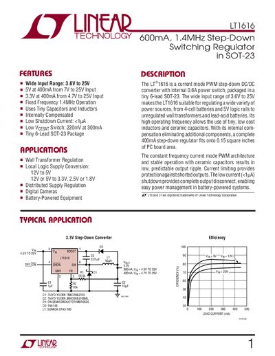
The LT1616 is a constant‑frequency, current‑mode step‑down (buck) regulator packaged in a 6‑lead SOT‑23. It operates from a wide input range of 3.6 V to 25 V and delivers up to 400 mA at 5 V or 3.3 V output, using an internal 600 mA power switch and external inductor and capacitors.
The document includes absolute maximum ratings, electrical characteristics, typical performance curves, pin descriptions, and detailed application guidance such as inductor and capacitor selection, layout recommendations, and a typical application circuit. It also lists related parts and package dimensions.
| Input Voltage Range | 3.6 V to 25 V |
|---|---|
| Output Voltage (5 V version) | 5 V at 400 mA from 7 V to 25 V input |
| Output Voltage (3.3 V version) | 3.3 V at 400 mA from 4.7 V to 25 V input |
| Switching Frequency | 1.4 MHz |
| Quiescent Current (no load) | 1.9 mA (typ) |
| Shutdown Current | < 1 pA |
| Switch Vcesat | 220 mV at 300 mA |
| Maximum Duty Cycle | 80 % typical, 87 % max |
The shutdown current can be less than 1 pA.
The regulator operates at a fixed frequency of 1.4 MHz.